It is a known limitation that at this point in time, the following cannot be published to PDF by 12d Synergy's CAD Print to PDF feature.
Civil3D objects
ECWs
Plots with transparency (CAD Print to PDF does not facilitate toggling on plot transparency. Hence, plans are printed without applying the transparency.)
A popular output format for drawings is PDF. 12d Synergy's CAD Print to PDF feature eliminates several steps as CAD Printing/Plotting happens on the server end. This means you do not need to download the drawing file to your local workspace, open the drawing(s) in your desired CAD application, Plot to PDF, then add it into 12d Synergy. It is all completed in one simple step.
12d Synergy's CAD Print to PDF feature can either use the default settings from the drawing file as the output method (configured in the CAD application) or you can set custom settings in the CAD Publish window within the 12d Synergy Client application.
1.1. Setting up your Publishing Environment within 12d Synergy
1.1.1. Prerequisites
If you have PDF files attached to your DWGs, you will need .NET version 4.8 installed on your server. If not, the PDFs may not display in your final outputs.
You can download .NET version 4.8 using the following link: https://dotnet.microsoft.com/download/dotnet-framework/net48.
1.1.2. Configuration Files
12d Synergy does not have access to the default or custom configuration files that are available to your CAD application. These can include CTB, STB, TTF and SHX files, which need to be added to the 12d Synergy Server.
Please see the CAD Fonts and Plot Style Files section for instructions about setting up access to these files from your 12d Synergy Administration application.
1.1.2.1. CTB & STB Files (For 12d Synergy V4.3 and below)
To publish using the standard CTB or STB files, they must be available on the 12d Synergy Server.
These files can be placed in a folder named CAD Publish Plot Styles, and the folder location must be specified in the 12d Synergy Administration application > System Settings > General Storage setting.
1.1.2.2. CTB & STB Files (12d Synergy V5.0 and above)
To publish using the standard CTB or STB files, they must be placed in a folder within the 12d Synergy Client application. The location of this folder must be specified in the 12d Synergy Administration application > System Settings > CAD Plot Styles Folder setting.
If there are any files in the sub-directories of the folder in which the CTB and STB files are saved, they will be ignored. Hence, all files must be stored in a flat structure in that folder.
1.1.2.3. SHX
Utilised SHX files should be placed in the folder called CAD Fonts in the 12d Synergy Client application. The location of this folder must be specified in the 12d Synergy Administration application > System Settings > General tab > CAD Fonts folder setting.
1.1.2.4. TTF
The True Type Font files (.ttf), available to the 12d Synergy Server are located in the C:\Windows\Fonts folder on the server machine for the account that runs the 12d Synergy Server. These files may differ with different versions of Microsoft Windows. To install any missing files or add more files, right-click the .ttf file to be added and select the Install for all Users option. The .ttf file is then copied to the C:\Windows\Fonts folder.
You must select the Install for all Users option and NOT the Install option to install and access the .ttf files.
Dragging and dropping the .ttf files in the C:\Windows\Fonts folder will NOT install the fonts. Hence, you cannot access them.
Depending on the version of Microsoft Windows that the server is running on, the server may need to be restarted before 12d Synergy has access to the .ttf files.
When using non-standard fonts in a DWG file, you need to add any utilised SHX or TTF font files to the 12d Synergy Server. This includes fonts that may be called up in your .lin file or blocks. If these fonts are not available, CAD may substitute the existing font for the standard font and the PDF output may contain text that is incorrect or is not correctly positioned.
1.1.2.5. Linetype files
Linetype files (.lin) can be customised to create different types of lines (patterns of dashes, dots, shapes, and spaces). These can also utilise font files. As such, these files are placed in a folder named CADFonts, the location of which is specified in the 12d Synergy Administration application > System Settings > General Storage setting.
1.1.3. Plotting with Network Xrefs
If you are referencing files that are stored on your local network rather than within 12d Synergy, 12d Synergy can still plot these files under the following conditions.
You are NOT using any reference data with a path that uses a mapped network drive such as S:. Instead, you must use a UNC path, which is of the format \\MyNetworkServer\LocationToData.
This is because mapped network drives are specific to individual users and are most likely not set up for the account that runs your 12d Synergy Server. Microsoft Windows may not guarantee the availability of a mapped network drive unless the user is physically logged onto the machine.The 12d Synergy service account also has access to read these Xref files from their local network location.
1.2. Publishing
1.2.1. To Publish to PDF within the 12d Synergy Client application
In the 12d Synergy Client application, right-click the intended drawing or drawings.
Select the CAD > Publish to PDF option.
.png)
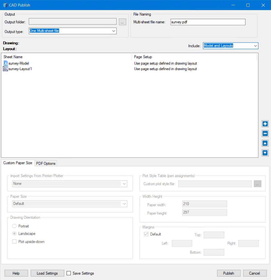
The CAD Publish window is displayed.You can adjust the settings in this window. Details of these settings are mentioned below in the Publish Settings section.
After configuring the required settings and order of sheets for publishing a CAD drawing to a PDF, you can save the configuration as a 12dSDSD file for subsequent use.
If you want to use a 12dSDSD file with the configuration you require to publish a CAD drawing file, you can load it when publishing the CAD drawing file.
If you want to publish the CAD drawing file with which you created a 12dSDSD file, simply right-click the required 12dSDSD file and select the CAD > Publish to PDF option. This will publish all the sheets of that 12dSDSD file to a PDF.
Click the Publish button.
The Select a Folder window is displayed.Browse and select a location to save the published PDF file/s in 12d Synergy and click the Select button.
Describe the change you are making in the following 12d Synergy prompt, and the file is published and saved as required.
1.2.2. How to Save a 12d Synergy Drawing Set Description(12dSDSD) File
This feature is available in 12d Synergy version 5.1.7 or later.
You can save the configuration and order of sheets when publishing a CAD drawing to a PDF in a 12d Synergy Drawing Set Description(12dSDSD) File. This file can be loaded to apply the same configuration and sheet order to another CAD drawing.
While publishing a CAD drawing to a PDF, after configuring the settings and ordering the sheets in the CAD Publish window, select the Save Settings check box.
.jpg)
Continue to publish the file.
After the file is published, the following Select a folder window is displayed.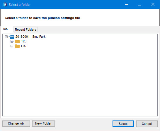
Browse and select the folder where you want to save the publish settings that you configured.
Click the Select button.
The Save As window is displayed.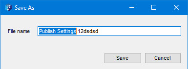
Enter a name for the 12dSDSD file and click the Save button.
The file is saved at the selected location. You can load this file when you want to apply the same settings for publishing a different CAD drawing.
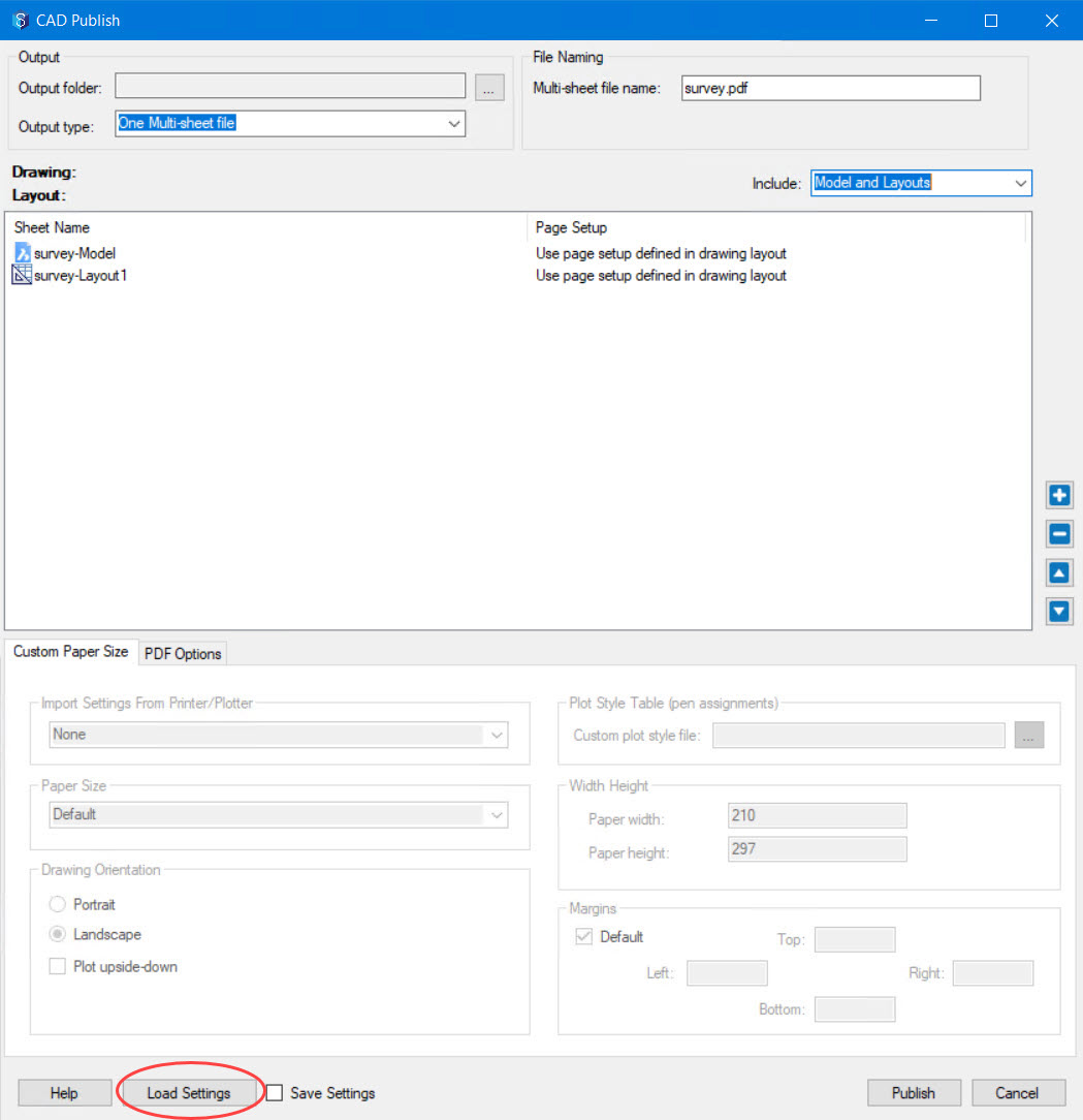
1.2.3. How to Load a 12d Synergy Drawing Set Description (12dSDSD) File
This feature is available in 12d Synergy version 5.1.7 or later.
You can apply a saved 12dSDSD while publishing a CAD drawing to a PDF. This file contains the configuration settings and sheet order that you have saved while publishing a previous CAD drawing. You can load the 12dSDSD file using the following procedure.
While publishing a CAD drawing to a PDF, click the Load Settings check box.
The Browse for a file <job name> window is displayed.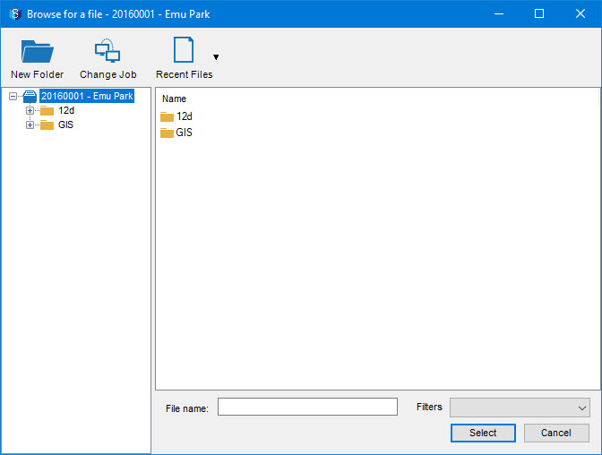
Browse and select the required 12dSDSD file and click the Select button.
The following prompt is displayed.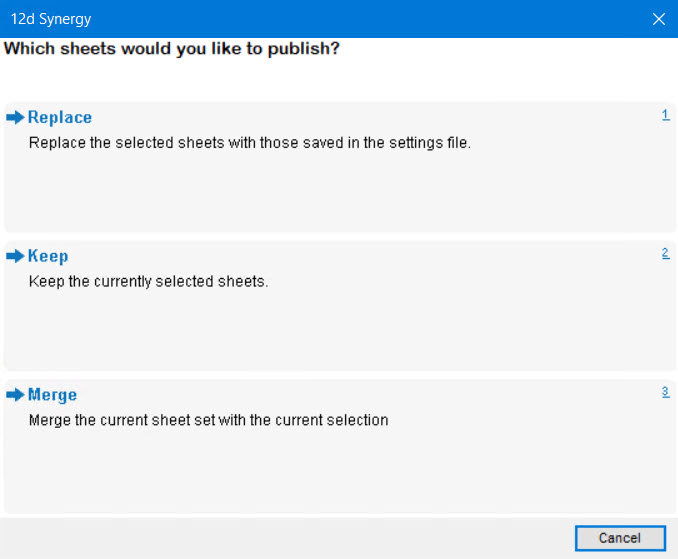
Do one of the following:
Select the Replace option to replace the sheets of the drawing file with those in the publishing settings file.
Select the Keep option to continue using the sheets in the selected drawing file and ignore those in the publishing settings file.
Select the Merge option to merge the sheet set of both, the drawing file and the publishing settings file.
Based on the option selected, the settings are displayed in the CAD Publish window.
Continue publishing the CAD drawing file.
1.2.4. Publish Settings
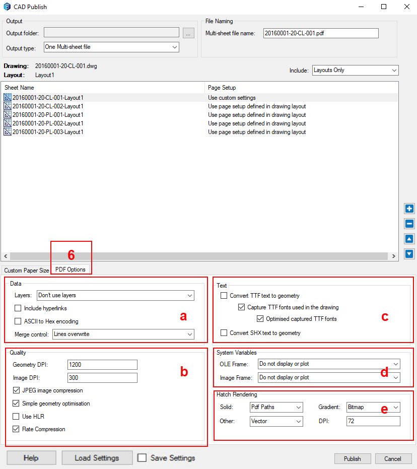
There are various settings that can be set/adjusted in the CAD Publish window. Details about these settings are further mentioned in sections cross-referenced by the labels in the image below.
CAD Publish window | Sections |
| 1.Output |
3.Include | |
b. Paper Size | |
e. Width Height | |
f. Margins | |

1. Output Section
In the Output section, click the ellipsis
 button to navigate and select the required 12d Synergy job and folder to save the published PDFs. By default, the current job is displayed for further navigation. You can change the job by clicking the Change job button.
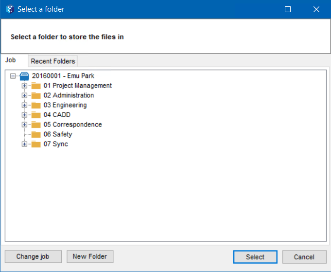
Select one of the following page layouts from the Output type list.
One Multi-sheet file
Single-sheet files
One file per drawing
The other settings are displayed based on the output type that you select.

2. File Naming Section
The available file naming format is based on the Output type you select from the list.
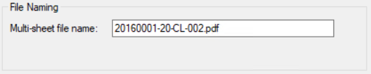
For the One Multi-sheet file Output type, the Multi-sheet file name box is displayed. Enter a name for your PDF in this box.
For the Single-sheet files Output type, the Layout name attribute box is displayed. This attribute can be used in a naming rule.

For the One file per drawing Output type, the layout name of the drawing file is used, and no other characters are allowed. Hence, nothing is displayed in the File Naming section.
3. Include
The Include section allows the user to select from the following options:
Models and Layouts
Layouts Only
Model Only
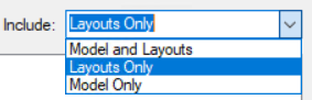
A system setting called CAD Publish include Model and/or Layouts is available in the 12d Synergy Administration application > System Settings tab > General tab > CAD section to set the Include: list to Layout Only, by default.
4. Sheet Name/Page Setup
This section is similar to the built-in Publish window in CAD. The drawings and layouts to be published are displayed here as a list. You can add, delete or reorder layouts using the ![]() ,
, ,
, ![]() and
and ![]() buttons. Custom page setup can be applied on an induvial sheet by selecting the listing entity in the Page Setup list.
buttons. Custom page setup can be applied on an induvial sheet by selecting the listing entity in the Page Setup list.

5. Custom Paper Size tab
These options become available only if the Use custom settings option is selected for the sheet in the corresponding Page Setup list. The Custom Paper Size tab allows you to specify details that may be familiar in a Standard CAD plot window.
Import Settings From Printer/Plotter section
When selecting a plotter/printer to import from, the available settings for that plotter/printer are adjusted in the following sections.

Paper Size section
The Paper Size list options are displayed based on the type of printer/plotter you select in the Import Settings From Printer/Plotter section.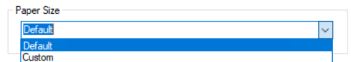
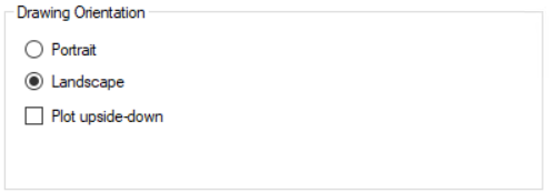
Drawing Orientation section
You can specify the output orientation in this section.
Plot Style Table (pen assignments) section
You can load a custom plot style file (.ctb) by clicking the ellipsis button and navigating to the location of the required file in the 12d Synergy Client application.

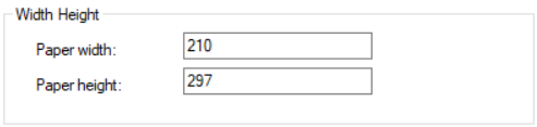
Width Height section
This section is activated when you select the Custom option from the Paper Size list. You can set the custom width and height here in millimetres.
Margins section
This section is activated when you select the Custom option from the Paper Size list. You can set the custom margins here in millimetres.
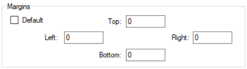
The default option is 0 for all margins. However, this can be set for each margin by clearing the Default checkbox and specifying a distance in each box.
Save and Load Settings
This section allows you to save the settings configured for publishing a drawing file to a PDF and load them when you are publishing the drawing files subsequently. The Save Settings check box must be selected to save the settings to a 12dSDSD file. While publishing another drawing file, you can click the Load Settings button to load the required 12dSDSD file to apply the settings saved in that 12dSDSD file. Note that you can have multiple 12dSDSD files to save different sets of settings that you wish to use for publishing later.
6. PDF Options tab
You can use this tab to configure advanced settings for the PDF you are publishing from your drawing file.
Data section
This section enables some embedded features in your PDF outputs.

Under the Layers list, you can identify whether or not your PDF file is embedded with layer information.
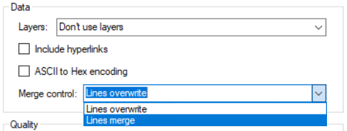
Any included hyperlinks can be embedded by selecting the Include hyperlinks checkbox.
You can enable the ASCII to Hex encoding by selecting the ASCII to Hex encoding checkbox.
You can define the line merge control from the Merge Control list.
Quality section
This section is for specifying the quality of the PDF output.
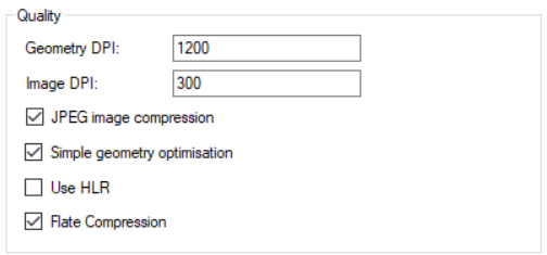
Adjust the Geometry DPI in the Geometry DPI box.
Adjust the Image DPI in the Image DPI box.
Enable the JPEG image compression by selecting the JPEG image compression checkbox.
Enable the geometry optimisation by selecting the Simple geometry optimisation checkbox.
Enable the use of HLR by selecting the Use HLR checkbox.
Apply Flat Compression by selecting the Flat Compression checkbox.
Text section
This section is for converting text entities in the PDF to geometry.

Select the Convert TTF text to geometry checkbox to enable the conversion of TTF text to geometry. There are two more related check boxes which are listed below.
Capture TTF fonts used in the drawing
Optimised captured TTF fonts
Select the Convert SHX text to geometry checkbox to enable the conversion of SHX text to geometry.
System Variables section
This section is for converting text entities in the PDF to geometry.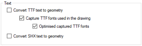
Select the Convert TTF text to geometry checkbox to enable the conversion of TTF text to geometry. There are two more related checkboxes which are listed below.
Capture TTF fonts used in the drawing
Optimised captured TTF fonts
Select the Convert SHX text to geometry checkbox to enable the conversion of SHX text to geometry.
Hatch Rendering section
This section is for handling the Hatch Rendering.
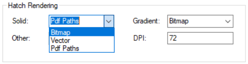
Each hatch type, Solid, Gradient and Other, has the following three settings.Bitmap
Vector
PDF Paths
The DPI box is for setting the Hatch DPI.